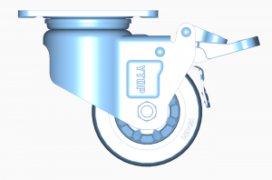
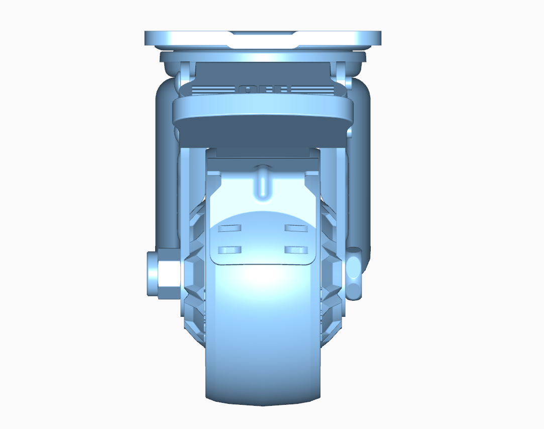
Universal wheel brake that is, universal joints, is to realize the variable angle power transmission of the machine, for the need to change the position of the direction of the drive shaft line, it is the automotive drive system of the universal transmission device “joint” components. Universal wheel brake and drive shaft combination, known as the universal joint transmission device. Universal wheel brake transmission device is generally composed of universal joints and drive shafts, and sometimes intermediate support, mainly used in some of the following positions: 1-universal joints; 2-drive shafts; 3-front drive shaft; 4-intermediate support. In a universal joint fit, the rotation of one component (output shaft) around its own shaft is driven by the rotation of another component universal joint (input shaft) around its shaft.
Universal wheel braking in the direction of torsion whether there is obvious elasticity can be divided into rigid universal joints and flexible universal joints. Rigid universal joints can be divided into unequal speed universal joints (commonly used for the cross shaft type), quasi-equal speed universal joints (such as duplex universal joints) and equal speed universal joints (such as ball-cage type universal joints) three. Universal joints in which the angle between the two shafts connected by the universal brake is greater than zero, and the output and input shafts transfer motion with a variable instantaneous angular velocity ratio, but the average angular velocities are equal.
Cross-axis type rigid universal joints are composed of universal joint fork, cross shaft, needle roller bearing, oil seal, set of simple, bearing cover and other components. The working principle is as follows: one of the rotating forks drives the other fork to rotate through the cross shaft, and at the same time, it can swing around the center of the cross shaft in any direction. During the rotation process, the needle rollers in the needle bearings can rotate to reduce friction. The shaft connected to the input power is called the input shaft (also called the active shaft), and the shaft output by the universal joint is called the output shaft (also called the driven shaft). A universal brake operates under conditions where there is an angle between the input and output shafts, where the angular velocities of the two shafts are unequal, and as a result can cause torsional vibration of the output shaft and the transmission components connected to it and affect the life of those components. It refers to a universal brake that transmits motion at equal instantaneous angular velocities at the designed angle and at approximately equal instantaneous angular velocities at other angles. It is subdivided into:
(a) Duplex type quasi-equal speed universal joints. It refers to the universal joint in which the length of the drive shaft in the universal joint equal speed drive is shortened to the minimum.
b) Bump type quasi-isochronous universal joints. By two universal joints and two different shapes of the bump composition. The two bumps are equivalent to the intermediate drive shaft and two cross pins in the duplex universal joint device.
(c) Three-pin type quasi-isochronous universal joints. It consists of two three-pin shafts, active eccentric shaft fork and driven eccentric shaft fork.
(d) Spherical roller type quasi-isokinetic universal joint. It consists of pin shaft, spherical roller, universal joint shaft and cylinder. The roller can move axially in the groove, playing the role of expansion spline. Roller and groove wall contact can transfer torque. Universal joints in which the output and input shafts connected by the universal brake transmit motion at always equal instantaneous angular velocities.
Post time: Feb-19-2024


